

Ensuring Reliability: The Importance of the Data Center Bypass Valve (Hot-Swappable Cooling Distribution Unit)
- 2026-08-14 09:44:27
- admin
- NO COMMENTS
Enhancing Data Center Reliability with Hot-Swappable Cooling Distribution Unit Bypass Valves
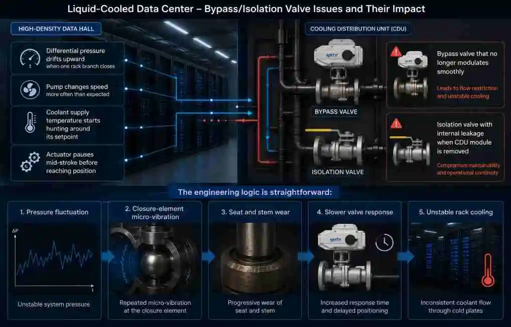
Inside a high-density data hall, cooling trouble rarely begins with a dramatic alarm. More often, an engineer notices a small change first: the secondary-loop differential pressure drifts upward when one rack branch closes, a pump changes speed more often than expected, or the coolant supply temperature starts hunting around its setpoint. Near the cooling distribution unit, an actuator may pause halfway through its stroke before finally reaching the commanded position.
These are not cosmetic issues. In a liquid-cooled data center, a restriction or unstable bypass path can reduce coolant flow through cold plates while servers continue generating heat. Engineers carrying out inspections often find one of two problems: a bypass valve that no longer modulates smoothly, or an isolation valve that allows slight internal leakage when a CDU module is removed for maintenance. Either condition can undermine operational continuity.
The engineering logic is straightforward:
Pressure fluctuation → closure-element micro-vibration → seat and stem wear → slower valve response → unstable rack cooling.
A second failure chain is equally important:
Repeated coolant-temperature cycling → elastomer compression set → small seal leakage → moisture near sensitive equipment → increased outage risk.
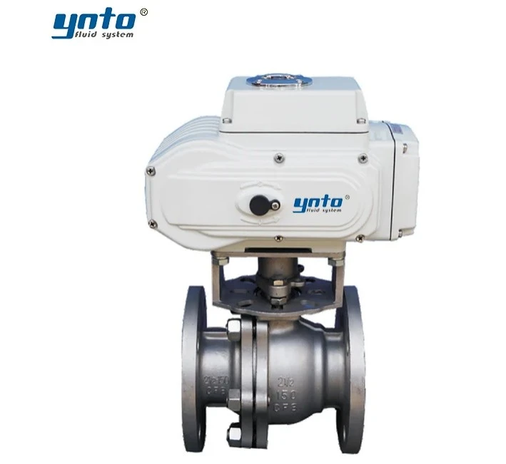
For facilities operating older imported CDUs, sourcing the original valve can be costly and slow. A properly engineered 1:1 replacement offers another option. The new valve can match the original connection dimensions, flow coefficient, pressure rating, actuator interface, feedback signal, and fail position—at a more practical price, without reducing required performance when the design is correctly verified.
Understanding the Bypass Valve
What Is a Bypass Valve?
A bypass valve provides an alternative route for coolant when the normal flow path is restricted, isolated, or temporarily unavailable. Within fluid management systems, it may divert flow around a heat exchanger, pump, filter, cold-plate manifold, or serviceable CDU module.
The valve may operate in a simple open-close mode, but many data center applications require controlled diversion. A three-way valve can direct coolant toward the active branch, return part of the flow through the bypass, or maintain minimum circulation while another component is isolated.
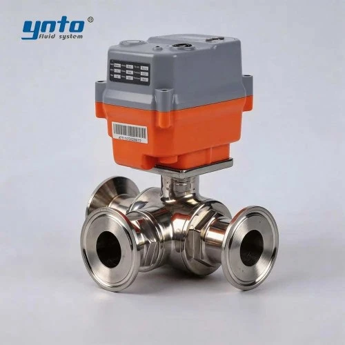
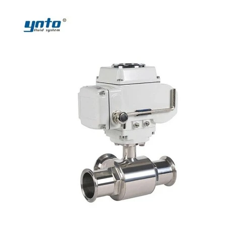
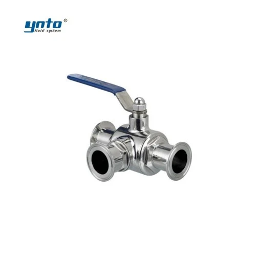
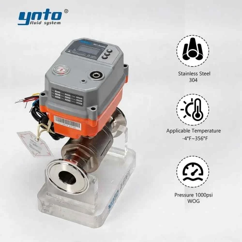
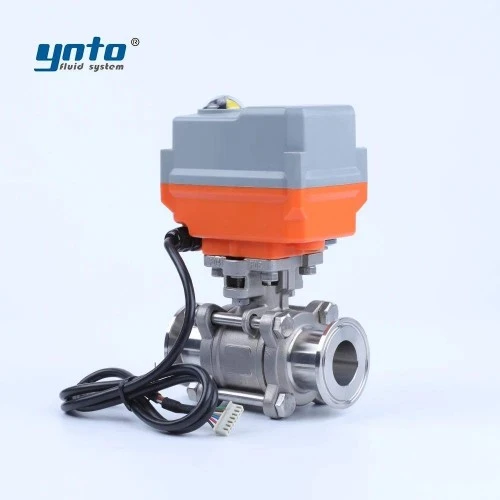
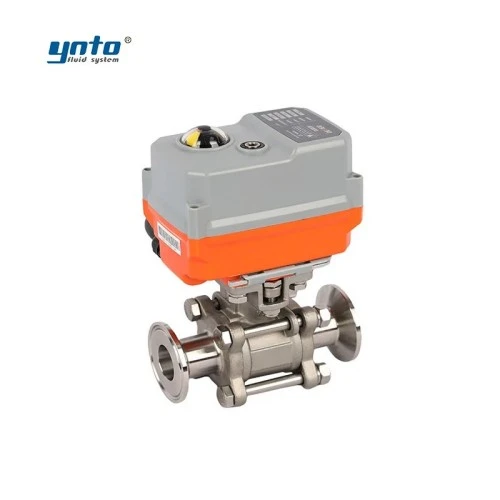
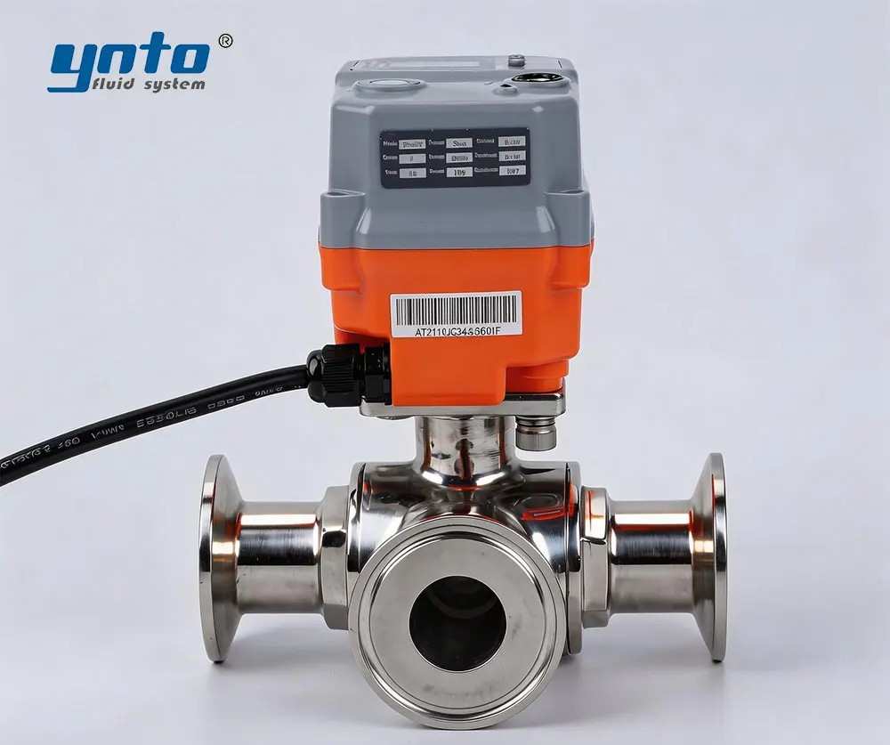
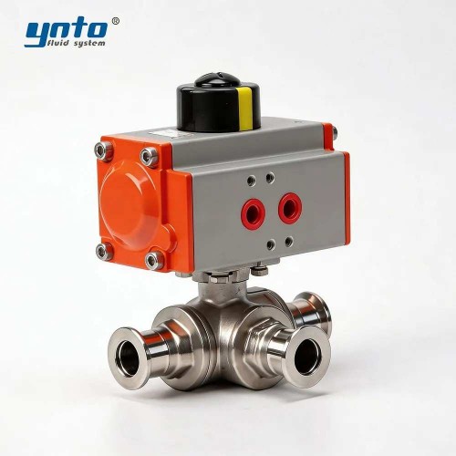
For compact, corrosion-resistant assemblies, an electric 316 stainless steel three-way clamp ball valve can provide L- or T-pattern diversion with automated control. Its 316 stainless steel construction and clamp connection are relevant where maintenance access, cleanliness, and fast removal matter. CNYNTO identifies the product for automated fluid-control applications and PLC/DCS integration.
A bypass valve should not be treated as an oversized relief device. Its required Cv or Kv must be calculated from the minimum acceptable coolant flow, available differential pressure, and expected operating states. If the bypass is too small, pressure rises when branch valves close. If it is too large, excessive coolant may avoid the heat-producing equipment.
Significance in Cooling Distribution Units
A CDU separates or manages the relationship between the facility-water loop and the technology-cooling loop serving servers, manifolds, and cold plates. Its functions may include pumping, heat exchange, filtration, temperature control, pressure regulation, coolant replenishment, leak detection, and communication with environmental control systems.
Modern CDUs commonly use redundant pumps, bypass loops, and intelligent controls to support continuous service. Eaton describes CDU designs with N+1 pump arrangements, automatic leak detection, coolant replenishment, and bypass capability for standby operation. Hot-swappable pumps, filters, or other internal components can then be serviced without shutting down the entire cooling system.
The bypass valve is what gives this redundancy a usable hydraulic path. If a pump is removed but the valve sequence does not maintain stable circulation, the hardware may be physically hot-swappable while the cooling process is not.
For an older CDU, a 1:1 replacement valve should therefore reproduce the original flow path and switching logic. Face-to-face dimensions alone are not enough. The replacement supplier must also verify port configuration, full-bore diameter, pressure loss, actuation time, allowable differential pressure, and leakage performance.
The Role of Fluid Management Systems
Maintaining Optimal Cooling
Stable liquid cooling depends on controlled flow through every operating rack. The CDU pump supplies pressure, but valves determine where the coolant goes and how quickly the system responds when the IT load changes.
During commissioning, a common sign of poor valve selection is temperature oscillation downstream of the CDU. The controller reduces valve opening because supply temperature is too low. Flow then falls too sharply, the return temperature rises, and the controller reverses its command. The valve continually hunts instead of settling.
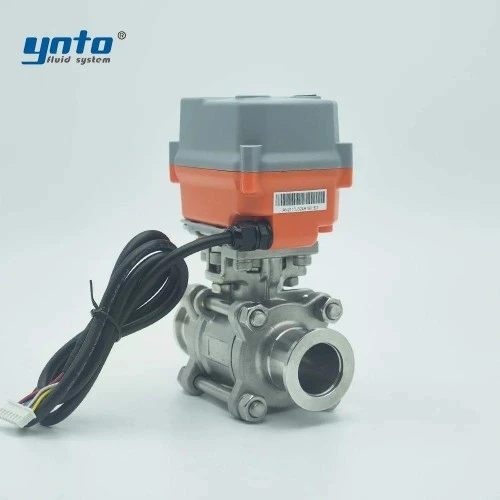
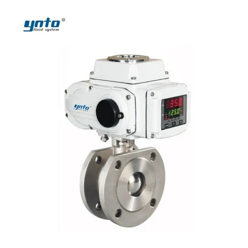
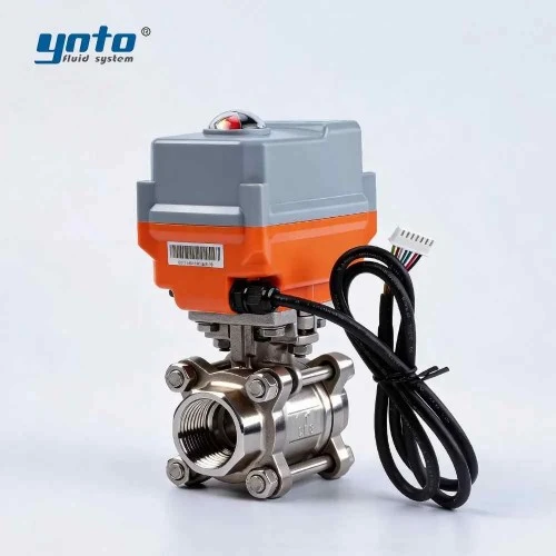
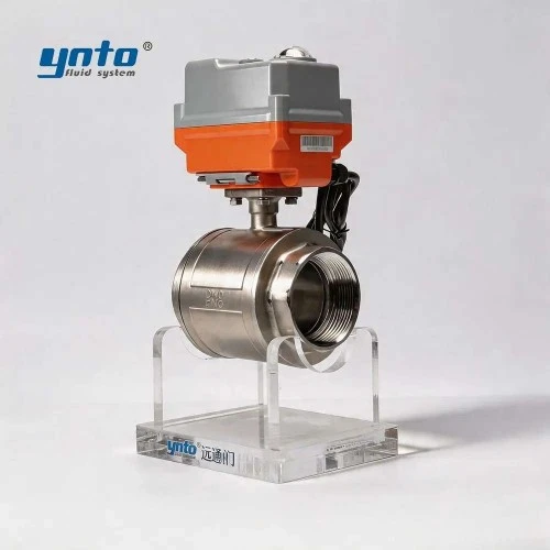
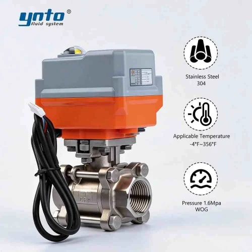
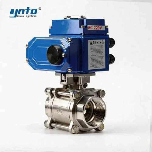
The problem may come from an oversized valve with poor authority, excessive actuator deadband, or a control characteristic that does not match the application. For smaller isolation branches, a two-way electric ball valve for water-flow control can support automated coolant isolation and proportional control configurations. The product range includes electric actuation and 4–20 mA control options suited to integration with monitoring systems.
Material compatibility also affects long-term stability. EPDM is widely used in water and water-glycol duties, while FKM may be selected where temperature or chemical resistance requirements are higher. PTFE provides low friction and broad chemical resistance, although its creep characteristics and seat-loading requirements must be considered.
Austenitic 316L stainless steel is often suitable for wetted parts where corrosion resistance and cleanliness are priorities. Carbon steel may remain practical on a treated facility-water side, particularly with an appropriate FBE coating. Duplex or Super Duplex is generally reserved for more severe chloride exposure, while Halar coatings may be considered for unusually aggressive coolant chemistry. Expensive materials should be specified from water-quality data, not marketing preference.
Integration with Environmental Control Systems
The bypass valve should communicate with the broader climate control system rather than operate as an isolated device. Useful inputs include supply and return temperature, differential pressure, pump speed, rack demand, leak status, and ambient dew point.
Dew-point control is especially important. If coolant temperature falls below the surrounding air’s dew point, condensation can develop on piping, manifolds, or cold plates. Eaton notes that temperature and humidity sensing are typically used to keep data center liquid-cooling equipment operating above condensation conditions.
For engineers working on site, the best control sequence is usually permissive-based. A service valve should not isolate a module until the bypass path is confirmed open. A standby pump should not start against a closed discharge valve. Likewise, a bypass should not close until the replacement component has reached stable flow.
Real-time status feedback makes these sequences verifiable. Without position feedback, the controller only knows that it issued a command. It does not know that the valve actually moved.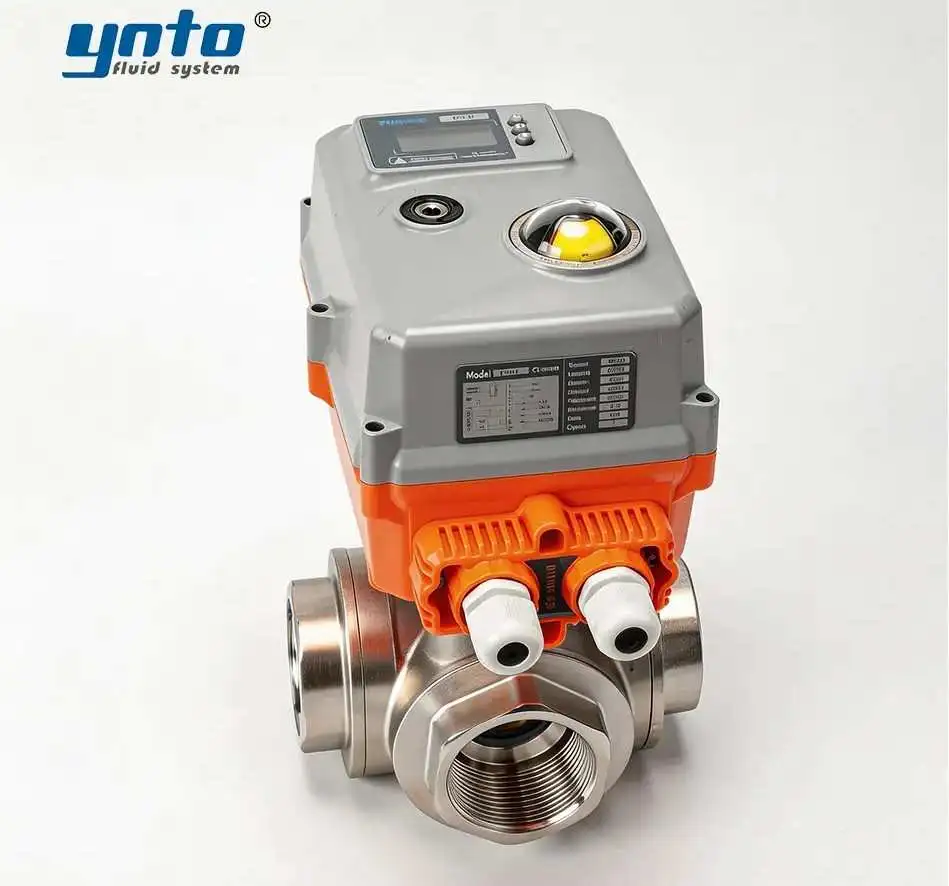
Hot-Swappability Features
Benefits for Operational Continuity
Hot-swappability means that a serviceable component can be replaced while the surrounding cooling system remains operational. In practice, this requires more than one valve. A complete arrangement normally includes upstream and downstream isolation, a functioning bypass, redundant pumping, non-spill connections, and validated control logic.
Quick-disconnect couplings used in direct liquid cooling can support connection and disconnection without shutting down the CDU. CEJN describes hot-swappable hand-mate and blind-mate couplings with spill-free operation, while its UQDB design includes redundant seals and misalignment tolerance for rack-level installation.
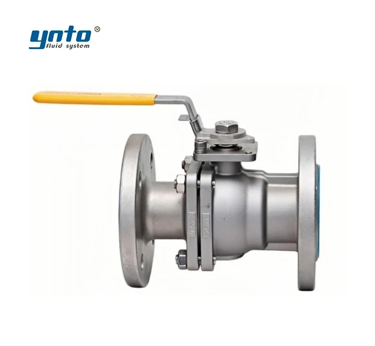
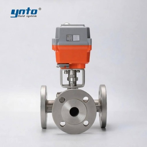
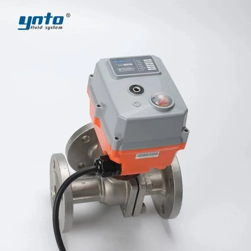
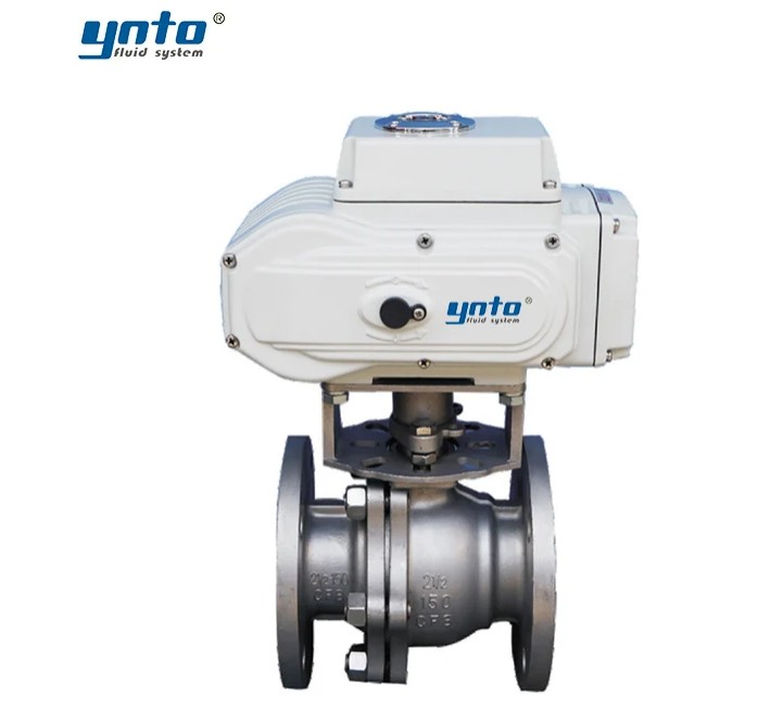
For a larger flanged bypass station, a high-performance three-way flanged ball valve can provide T-pattern or L-pattern flow switching. Such a configuration is useful where one route must be isolated while coolant is diverted through a standby branch.
The practical value is reduced maintenance exposure. Instead of shutting down the full CDU, draining the technology loop and interrupting cooled equipment, the operator can isolate one serviceable branch while the remaining circuit stays active.
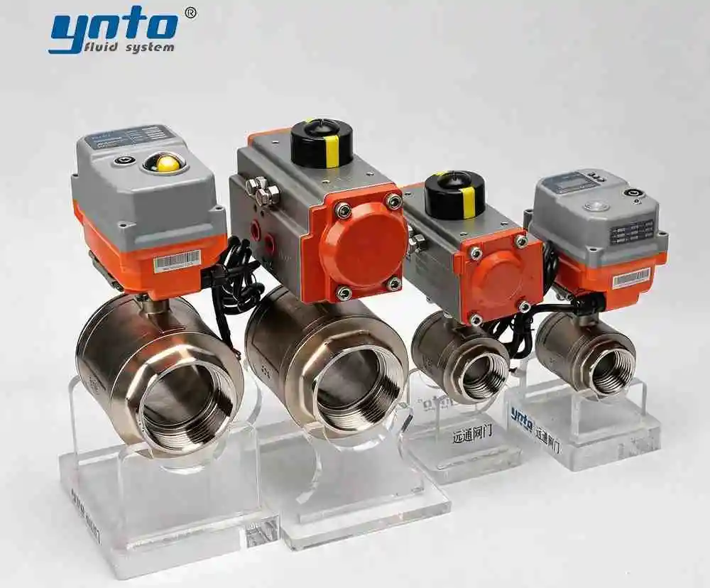
A 1:1 replacement is particularly attractive here. If the original imported three-way valve has a proprietary stem height, unusual flange spacing, or specific actuator orientation, CNYNTO can manufacture a corresponding replacement from drawings, a physical sample, or verified site dimensions. The objective is drop-in compatibility at a lower procurement cost—not a simplified substitute with reduced capacity.
Real-Time Monitoring Capabilities
Real-time monitoring should capture more than valve-open and valve-closed signals. Stroke time, commanded position, actual position, motor current, and actuator fault status can reveal deterioration before flow is lost.
An actuator that normally completes its stroke in six seconds but later requires ten may be experiencing increased seal friction, misalignment, or deposit formation. A valve that repeatedly overshoots its target may have excessive backlash or poorly tuned control parameters.
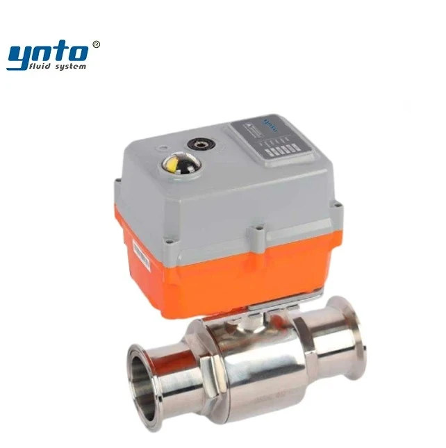
The YT-02 electric valve actuator is available in switching, regulating, bus, and other control arrangements. CNYNTO specifies precise control and application in refrigeration, air-conditioning equipment, and data center systems, making the series relevant to replacement projects requiring feedback, remote operation, or upgraded automation.
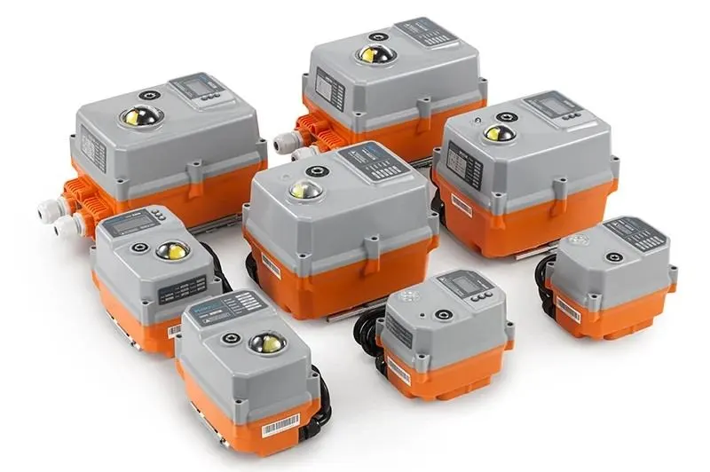
When replacing an imported actuator, the engineering team should confirm supply voltage, signal type, torque, duty cycle, enclosure rating, manual override, fail-safe behavior, and mounting interface. Matching the old cable colours is not enough.
ISO 5211:2026 specifies attachment requirements and torque-reference values for part-turn valve actuators. Using a standardized interface simplifies future maintenance and reduces dependence on a proprietary mounting arrangement.
Enhancing Data Center Efficiency
Energy-Efficient Cooling Strategies
A cooling system wastes energy when valves create unnecessary pressure loss. Every restrictive fitting raises pump head. The pump then consumes more power to maintain the required rack flow.
Low-pressure-drop quick couplings and full-port valves help reduce this burden. CEJN notes that lower pressure drop can allow smaller pump selection and lower running energy costs in liquid-cooling systems.
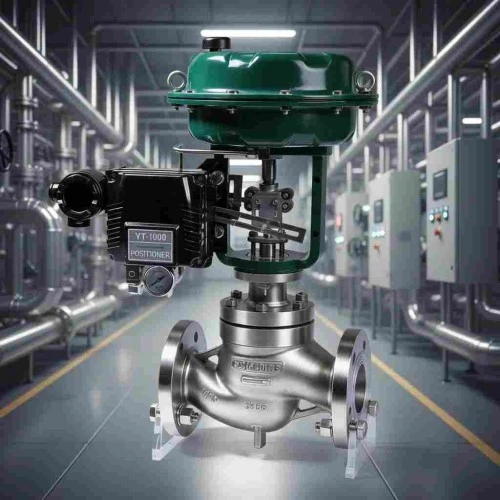
For modulating duties, an electric single-seat control valve can regulate flow or pressure from a control signal. CNYNTO offers the design with 4–20 mA input across multiple sizes and pressure levels. In a CDU, final sizing must still be based on the coolant flow, differential pressure, control range, and allowable leakage rather than nominal diameter alone.
Energy-efficient cooling also depends on sequencing. Pumps should not operate at maximum speed while control valves throttle away excess pressure. A better arrangement coordinates pump speed with differential-pressure feedback and valve position. When most valves are nearly closed, pump speed can decrease. When rack demand rises, the system increases flow gradually.
Climate Control System Innovations
Current climate control systems increasingly combine liquid-loop data with IT load information. The CDU controller can anticipate a change in thermal demand rather than waiting for coolant temperature to drift.
Digital models also help engineers test failure conditions before commissioning. Simulated pump loss, valve sticking, sensor failure, and rapid rack-load changes reveal whether the bypass path can protect the system without creating pressure shock.
Future 1:1 replacement valves can improve older CDUs without forcing a full system redesign. A replacement may retain the original mechanical envelope while adding brushless actuation, faster feedback, Modbus communication, power-off reset, or more precise modulating control.
This upgrade path is commercially important. Imported CDU valves are sometimes priced as proprietary spare parts even when their hydraulic function is conventional. By reverse-engineering the critical dimensions and operating parameters, a manufacturer can supply a more affordable replacement while preserving the performance required by the system.
Challenges in Implementation
Common Pitfalls
The first mistake is assuming that identical flange dimensions guarantee interchangeability. A replacement may bolt into place but produce a different pressure drop, port sequence, or actuator response.
The second is selecting seals without checking the coolant formulation. Glycol concentration, corrosion inhibitors, biocides, and cleaning chemicals can change elastomer compatibility.
The third is ignoring trapped pressure. A hot-swappable branch may remain pressurized between two closed valves. Maintenance procedures should include a controlled bleed or drain point, verified zero pressure, and leak containment.
Another common problem is insufficient actuator margin. Coolant deposits, seal aging, and differential pressure all increase required torque. An actuator sized exactly to clean-valve torque may stall after several years.
Solutions and Best Practices
A reliable 1:1 replacement project begins with the original datasheet, dimensional drawing, and control schematic. Where these are unavailable, the supplier should receive detailed measurements, photographs, nameplate data, and, ideally, a sample valve.
The comparison should cover face-to-face length, connection standard, flow coefficient, pressure rating, temperature range, wetted materials, seat compound, actuator torque, control signal, feedback, fail position, and leakage requirement.
Pressure safety must be verified through recognized requirements. ASME B16.34-2025 covers pressure-temperature ratings, materials, dimensions, testing, and marking for applicable industrial valves. API 598 provides an established framework for valve inspection and testing, while DIN EN 558:2022 standardizes face-to-face dimensions for flanged metal valves.
Factory acceptance testing should reproduce the required operating sequence. The team should verify shell integrity, seat leakage, actuator travel, feedback accuracy, fail-safe response, and switching logic before shipment.
Conclusion
A data center bypass valve is not merely an auxiliary fitting. It protects coolant circulation when pumps, filters, heat exchangers, or CDU modules are isolated, and it enables hot-swappable maintenance without sacrificing rack cooling.
Its reliability depends on correct hydraulic sizing, compatible materials, adequate actuator margin, and integration with real-time monitoring. Pressure fluctuations, thermal cycling, and poor coolant chemistry all leave recognizable signs long before complete failure. Engineers who track differential pressure, stroke time, and valve position can intervene early.
For facilities using aging imported CDUs, a YNTO 1:1 replacement valve can reproduce the original valve’s critical dimensions, control interface, and operating performance at a more competitive price. The replacement should be engineered and tested—not merely copied by appearance. When those steps are completed properly, lower procurement cost does not require lower system reliability.
References
Eaton, “Coolant Distribution Units” and CDU design guidance.
CEJN, data-center liquid-cooling and hot-swappable coupling guidance.
Supermicro, CDU connection guidance for liquid-cooled server systems.
ASME B16.34, ISO 5211, API 598, and DIN EN 558 valve standards.
.png?imageMogr2/format/webp)
- 2026-09-30 08:25:23
- 2026-09-28 10:28:43
- 2026-09-21 15:23:44